
The 24-pin ATX power connector is the backbone of modern desktop computer power supply systems, serving as the critical interface between the power supply unit (PSU) and the motherboard. Introduced with the ATX 2.0 specification in 2003, this connector replaced the earlier 20-pin design to meet the growing power demands of advanced hardware components like PCIe graphics cards and multi-core CPUs. This article provides a comprehensive analysis of its pinout, signal transmission mechanisms, and design innovations.
The transition from the 20-pin to the 24-pin connector addressed two key challenges:

Power Capacity: The 24-pin design added four new pins to deliver higher current, particularly on the +12V rail, which powers high-performance CPUs and GPUs .
Stability: Additional ground pins reduced electromagnetic interference (EMI) and improved voltage regulation .
While the 20-pin connector supported up to 250W, the 24-pin connector allowed PSUs to handle 300W+ configurations, making it suitable for modern gaming and workstation setups .
The 24-pin connector follows a standardized pinout defined by the ATX specification, with color-coded wires for easy identification :
| Pin | Color | Voltage/Signal | Function |
|---|---|---|---|
| 1 | Orange | +3.3V | Power for low-voltage components (e.g., USB, chipset) |
| 2 | Orange | +3.3V | Redundant +3.3V supply |
| 3 | Black | GND | Ground |
| 4 | Red | +5V | Power for legacy peripherals (e.g., HDDs, optical drives) |
| 5 | Black | GND | Ground |
| 6 | Red | +5V | Redundant +5V supply |
| 7 | Black | GND | Ground |
| 8 | Gray | Power Good (PG) | Indicates stable voltages (sent after PSU self-tests) |
| 9 | Purple | +5VSB | Standby power for wake-on-LAN and USB charging (active even when the PC is off) |
| 10 | Yellow | +12V | Primary power for CPU and GPU |
| 11 | Yellow | +12V | Redundant +12V supply |
| 12 | Orange | +3.3V | Power for PCIe slots and memory |
| 13 | Orange | +3.3V | Redundant +3.3V supply |
| 14 | Blue | -12V | Legacy support for serial ports (rarely used today) |
| 15 | Black | GND | Ground |
| 16 | Green | PS-ON# | Power-on signal (low to activate PSU) |
| 17 | Black | GND | Ground |
| 18 | Black | GND | Ground |
| 19 | Black | GND | Ground |
| 20 | White | -5V | Optional (removed in newer ATX versions) |
| 21 | Red | +5V | Power for PCIe slots and peripherals |
| 22 | Red | +5V | Redundant +5V supply |
| 23 | Red | +5V | Redundant +5V supply |
| 24 | Black | GND | Ground |
The PSU remains in standby mode until the motherboard sends a low-level signal to the PS-ON# pin (pin 16). This triggers the PSU to activate all voltage rails. When the system shuts down, the motherboard releases the signal, and the PSU enters standby .
The Power Good (PG) signal (pin 8) is critical for system stability. After the PSU stabilizes all voltages (within ±5% tolerance), it sends a +5V PG signal to the motherboard. This signal must remain high for at least 16ms after AC power loss to allow the system to safely shut down .
Some PSUs use remote sensing on the +3.3V and +5V lines (pins 12–13 and 21–23) to compensate for voltage drops in long cables. This ensures accurate voltage delivery to the motherboard .
Keying Mechanism: The connector’s asymmetric shape prevents incorrect insertion, protecting against short circuits .
Modular Design: Many PSUs feature detachable 20+4-pin connectors, ensuring compatibility with older motherboards while supporting modern power requirements .
Multi-Rail Architecture: ATX 2.2 introduced independent +12V rails to isolate power delivery to the CPU and GPU, reducing interference .
Backward Compatibility: A 24-pin PSU can power a 20-pin motherboard by leaving the extra four pins unconnected. Conversely, a 20-pin PSU may struggle with high-power systems due to limited +12V capacity .
Pin Oxidation: Corrosion on pins can cause intermittent connectivity. Regular cleaning with contact cleaner is recommended .
Overloading: Exceeding the rated current on any rail (e.g., using a 20-pin PSU for a high-end GPU) may trigger overcurrent protection or system instability .
While ATX 3.0 (2022) introduced the 12VHPWR connector for PCIe 5.0 GPUs, the 24-pin connector remains unchanged. This ensures legacy compatibility while supporting next-gen hardware .
The 24-pin ATX connector is a testament to the balance between innovation and backward compatibility. Its standardized pinout, robust signal mechanisms, and modular design have made it the industry standard for over two decades. As PC hardware evolves, the 24-pin connector continues to adapt, ensuring reliable power delivery for everything from budget builds to high-end workstations. By understanding its pinout and signal logic, users can troubleshoot issues, optimize performance, and make informed decisions when selecting PSUs and motherboards.
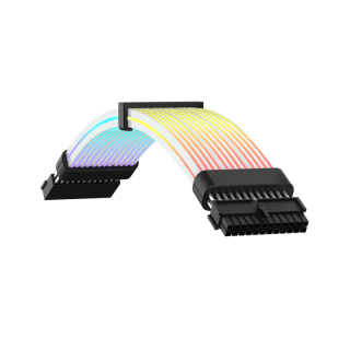
PSU extension cable, ARGB light. Description: MB 24PIN. Package: 40PCS/CTN.

